
In order to promote public education and public safety, equal justice for all, a better informed citizenry, the rule of law, world trade and world peace, this legal document is hereby made available on a noncommercial basis, as it is the right of all humans to know and speak the laws that govern them.
US 761
First Edition
2007-12-19
Reference number
US 761:2007
© UNBS 2007
i|
Compliance with this standard does not, of itself confer immunity from legal obligations A Uganda Standard does not purport to include all necessary provisions of a contract. Users are responsible for its correct application |
|
© UNBS 2007 All rights reserved. Unless otherwise specified, no part of this publication may be reproduced or utilised in any form or by any means, electronic or mechanical, including photocopying and microfilm, without prior written permission from UNBS. Requests for permission to reproduce this document should be addressed to The Executive Director |
| Page | |||
| Foreword | iv | ||
| 1 | Scope | 1 | |
| 2 | Terms and definitions | 1 | |
| 3 | Symbols (and abbreviated terms) | 2 | |
| 4 | Material requirements | 2 | |
| 4.1 | General | 2 | |
| 4.2 | Cladding | 2 | |
| 4.3 | Ceramic liner | 3 | |
| 4.4 | Pot rests | 3 | |
| 4.5 | Insulation | 3 | |
| 5 | Workmanship and constructional requirements | 3 | |
| 5.1 | Construction | 3 | |
| 5.2 | Firing of the ceramic liner and insulation media/material | 6 | |
| 5.3 | Assembling | 6 | |
| 5.4 | Grate | 8 | |
| 5.5 | Legs | 8 | |
| 6 | Finish | 8 | |
| 7 | Marking and packaging | 9 | |
| 7.1 | Marking | 9 | |
| 7.2 | Packaging | 9 | |
| 8 | Test requirements | 9 | |
| 8.1 | Heat transfer tests | 9 | |
| 8.2 | Safety test requirement | 9 | |
| 8.3 | Thermal conductivity test for ceramic liner | 9 | |
| 9 | Acceptance criteria | 9 | |
| 9.1 | Acceptance criteria for biomass stoves | 9 | |
| 9.2 | Criteria of acceptance of insulant | 10 | |
| 9.3 | Acceptance criteria for ceramic liner | 10 | |
| Annex A (normative) Heat transfer test | 11 | ||
| A.1 | Equipment and materials | 11 | |
| A.2 | Materials | 11 | |
| A.3 | Applicability of test | 11 | |
| A.4 | Procedure | 12 | |
| Annex B (normative) Thermal shock/stress resistance test | 14 | ||
| Annex C (normative) Water boiling test data form | 15 | ||
| Annex D (normative) Determination of thermal conductivity of ceramic liner | 17 | ||
| D.1 | Sample preparation | 17 | |
| D.2 | Procedure | 17 | |
| D.3 | Data form for results for thermal conductivity test | 18 | |
| Annex E (normative) Operating instructions | 19 | ||
| Bibliography | 21 | ||
Uganda National Bureau of Standards (UNBS) is a parastatal under the Ministry of Tourism, Trade and Industry established under Cap 323, of the Laws of Uganda. UNBS is mandated to co-ordinate the elaboration of standards and is
The work of preparing Uganda Standards is carried out through Technical Committees. A Technical Committee is established to deliberate on standards in a given field or area and consists of representatives of consumers, traders, academicians, manufacturers, government and other stakeholders.
Draft Uganda Standards adopted by the Technical Committee are widely circulated to stakeholders and the general public for comments. The committee reviews the comments before recommending the draft standards for approval and declaration as Uganda Standards by the National Standards Council.
Committee membership
The following organisations were represented on Mechanical Engineering and Metallurgy Standards Technical Committee, UNBS/TC 4, in the preparation of this standard:
Energy efficiency stoves — Household biomass stoves — Performance requirements and test methods
This Uganda Standard specifies the performance and test methods for household biomass stoves. The household stoves covered in this standard utilize the following biomass fuels namely charcoal, wood, baggasse, husks, plant shells and any other biomass.
For the purpose of this standard, the following apply.
device where biomass fuel is burnt to produce heat for cooking purpose, (see Figure 1)
organic products of agriculture and forestry systems used as primary energy. It includes wood fuel, combustible vegetable materials which includes agricultural waste and animal waste.
proportion of latent heat in a fuel transferred as heat to a working fluid (water)
ratio of energy transferred to working fluid (water) divided by the energy generated by burning fuel. It is also the thermal efficiency.
any clay which has been fired and ground to particle sizes less than 0.5 mm (mesh size 10)
mixture of insulation and binding materials that is used between the ceramic liner and cladding to hold them two together firmly and reduce heat loss
heat flow per unit area developed under unit temperature gradient
1moulded and fired clay that give heat retention properties to the stove
remaining product after complete combustion of biomass fuel
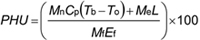
| Cp | = | Specific heat capacity of water (kJ/kg/°C) |
| Ef | = | Calorific value of the fuel (kJ/kg) |
| HPP | = | High power phase |
| K | = | Kelvin temperature scale (Absolute temperature) |
| L | = | Latent heat of vaporization (kJ/kg) |
| LPP | = | Low (simmering phase of heating) power |
| Me | = | Mass of water vaporized (kg) |
| Mf | = | Weight of fuel burned (kg) |
| Mn | = | Mass of water (kg) |
| O.P | = | Ordinary Portland cement |
| PHU | = | Percentage of heat utilized or thermal efficiency |
| Tb | = | Boiling temperature of the water (°C) |
| To | = | Starting temperature of the water (°C) |
All components of a household biomass stove shall be manufactured from materials which comply with the relevant Uganda Standards.
The cladding used in the manufacture of household biomass stoves shall be from a mild steel sheet (or any other steel) with a minimum thickness of 0.60 mm (Gauge 22) and maximum thickness of 1.20 mm (Gauge 18).
2| Gauges | Nominal thickness, mm |
|---|---|
| 22 | 0.63 |
| 20 | 0.80 |
| 18 | 1.00 |
The ceramic liner used in the manufacture of stoves shall be made from suitable pottery clay that has been fired as specified in 5.1.
Pot rests for charcoal stoves shall be made from mild steel bars of minimum diameter (5.00 mm for solid bars and 1.5mm diameter for hollow sections). Pot rests for complete ceramic stoves shall be of same material.
The insulation between the steel sheet or cladding and ceramic liner shall be made of various mixtures of material as described in Table 2. Any other material mixtures may be used provided that they meet the requirements of 8.4.
| Material | Ratio (Volume) |
|---|---|
| O.P Cement — Vermiculite | 1:3 |
| O.P Cement — Diatomite | 1:3 |
| O.P cement — Rice husks ash | 1:4 |
| O.P cement — Sand ash | 2:1:6 |
For the household biomass stoves in Figures 1 and 3, (two-component parts) the ceramic liner shall be assembled into steel plate cladding using insulation materials specified in Table 2. The other types of biomass stoves as described in Figures 2, 4 and 5 shall be assembled into any other utilizing materials. The stoves shall be of robust construction and stable.
3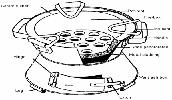
Figure 1 — Illustration of a typical household biomass stove

Figure 2 — Single ceramic household biomass stove for wood (used in the manufacture of wood stove with cladding in Figure 3 and also wood stoves in Figure 4 and Figure 5).
NOTE Design and dimensions of fixed stoves shall vary in accordance with purchaser/user instructions.
4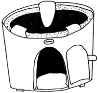
Figure 3 — Example ceramic wood stove

Figure 4 — Example single ceramic household biomass stove for wood as installed
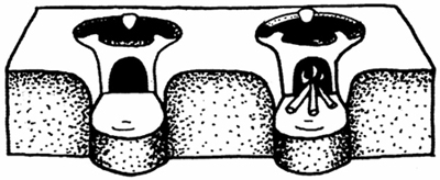
Figure 5 — Example double ceramic biomass cook-stove for wood as installed
5The ceramic liner shall be uniformly fired at 700 °C – 900 °C in the firing facility.
The liner shall be assembled into the cladding as illustrated in Figure 2 and using the insulant specified in Table 2. The same material shall be used to insulate the base of the ash box as illustrated in Figure 2. The other types of assembly shall comply with 4.2.

Figure 6 — Top view of stove
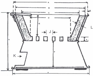
Figure 7 — Cross sectional view of the charcoal stove (view x-x)
6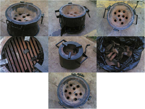
Figure 8 — Photographic representation of biomass stoves
7| Stove parts | Size, mm |
||
|---|---|---|---|
| Small | Medium | Large | |
| Bottom and top diameter of cladding, A | 250 – 260 | 280 – 290 | 300 |
| Overall height, h | 200 | 220 ± 10 | 230 |
| Top inside diameter of liner, C | 215 | 230 | 240 |
| Base inside diameter of liner, D | 150 | 165 | 175 |
| Fire box depth, E | 60 | 90 | 90 |
| Ash box depth, F | 60 | 90 | 90 |
| Grate diameter, D | 150 | 165 | 175 |
| Grate thickness, tc | 20 | 20 | 20 |
| Grate hole diameter, J | 20 | 20 | 20 |
| Inlet air door, K | 80 × 120 | 100 × 130 | 100 × 130 |
| Thickness of ceramic liner, L | 20 | 20 | 20 |
| Thickness for insulation, M | 15 | 15 | 15 |
The grate shall have holes separated by material of minimum diameter 15 mm. Hole sizes shall be 10 mm -20 mm.
Each stove shall be provided with minimum three legs measuring 20 mm in height and shall be spaced at equidistance for stability. Legs shall be of minimum thickness 1.5 mm.
All component parts of the stove shall be protected against corrosion by a suitable anticorrosion coating and shall be smooth and free from defects such as cracks, sharp edges or burrs.
The stove and its component parts shall be free of defects that adversely affect the appearance, performance and safety aspects during use.
The liner shall not be painted.
8The stoves manufactured shall be marked with the name and/or trademark or any other means of identifying the manufacturer, vendor or distributor of the biomass stoves.
Stoves shall be packaged in cartons in order to protect them while in storage and transportation. The biomass stoves shall be supplied with a hang tag or label with the wording “FRAGILE — HANDLE WITH CARE”.
The biomass stoves shall be supplied with an instruction leaflet which shall be in pictorial form as shown in Annex E.
Stoves selected at random shall undergo a heat transfer test in accordance with Annex A. A complete heat transfer water boiling shall comprise of two phases:
The outside surface temperature of the stove body shall not be high so as to cause burns when it is in use or when handling it. Outside surface temperatures of not more than 45 °C shall be considered appropriate for purposes of human safety.
The ceramic liner shall be tested for thermal conductivity as specified in Annex D.
Biomass stoves shall comply with tests in Annex B. The ceramic liners shall not crack due to heating and cooling cycles developed due to thermal stress. The more the number of cycles the liner endures, the better it is in resisting thermal shocks. As the test is extremely severe, a liner which can withstand five cycles can be considered to be made from a clay mix which is thermal shock resistance. As the stove is used over a period of time, the ceramic liner should withstand many cycles of heating and cooling without cracking.
Biomass stoves, which comply with the requirements of Clause 4, Clause 5, Clause 6, 8.2 and tests in Annexes A, B, and C, shall be accepted. Stoves, which have been tested in accordance with Clause 8 and Annex A and have achieved PHU of more than 30 % at power output of 3 kW, shall be accepted.
9The insulant shall be considered to meet the requirements of this standard if, when the stove is in use, the outside surface temperature does not exceed 45 °C. The insulation and binding materials shall be in accordance with Table 2.
A ceramic liner shall be considered to have met the requirements of this standard if its thermal conductivity value does not exceed 2.5 WK-1m-1 at 500 °C when determined in accordance with the procedure specified in Annex D.
10(normative)
Stoves
Aluminium pots and lids
Weighing balances, two with an accuracy of 10 g and a capacity of 15 kg
Electronic balance, accuracy to 1 g for weighing charcoal
Stop-watch
Mercury thermometers, of up to 105 °C and accuracy to ± 1 °C
Moisture content measuring device, of accuracy to 1 %
Gauge, for removing charcoal and test sheet form
Wood (cypress), of 2 cm diameter pieces
Water, 3 L
Kerosene/kindling
Match box/lighter/source of fire
The test is used to determine
Factors that can be accurately fixed in water boiling tests are:
Weigh the empty pot and lid.
Weigh the pot, lid and the specified amount of water.
Note the initial water and room temperature.
Weigh 2 kg of wood. Measure its moisture content which should be the same for the entire tack of wood that is between 10 % – 15 %.
Insert wood into the stove and spill about 10 mL of kerosene over the wood or use balls of paper. This is a common practice used in lighting stoves.
Ignite the wood with a match. Place the pot with its contents on the stove and start the stopwatch. This marks the start of the HPP.
Bring the water to the boil as rapidly as possible and at the same time record the water temperatures at intervals of 5 min. Also record the number of times wood is added.
Note the time water starts to boil. Open a gap of about 3 cm for water to evaporate off and continue at the same burning rate for another 15 min. This marks the end of the HPP.
Weigh the pot and its contents.
Remove the remaining wood from the stove and knock off charcoal from the ends. Weigh the wood left and also the charcoal produced during the HPP.
Record all the data in the water boiling test data sheet (see Annex C).
Place the wood and charcoal back into the stove. Put the pot and its contents back on the stove and re-light the wood by vigorous blowing.
Note the temperature of the water and start the clock. This marks the start of the LPP. A gap of about 3 cm is left and care is taken such that the water temperature is within – 2 °C of the boiling point.
The LPP is continued for a period of 60 min with water temperature being taken after every 5 min.
At the end of LPP, weigh the pot and its contents, the wood remaining and also the charcoal produced. Record the data in the data sheet.
Calculate the Percentage Heat Utilized (PHU) both in the HPP and LPP. PHU of over 30 % at power output of about 3 kW is considered good.
12A series of five tests shall be done per stove and the average values computed for comparison purposes. A table of calorific values of wood at different moisture contents shall be made available.
If not there, the value has to be determined using the bomb calorimeter. The water boiling tests are also used in testing charcoal stoves.
Data collection and report shall be made on water boiling test data forms specified in Annex C.
13(normative)
To test whether ceramic liners made from particular clay mix are thermal shock resistant, the liners shall be heated to temperature ranging 800 °C – 900 °C and then immersed in cold water at room temperature. These temperatures are attained in fireboxes when in use. This is repeated several times until the liner cracks. The heating can be done using a gas flame or an electric kiln.
As the test is extremely severe, a liner which can withstand five cycles shall be considered to be made from a clay mix that is thermal shock resistant.
14(normative)
| Test Number | Average | |||||
|---|---|---|---|---|---|---|
| Wf 1 (kg) | ||||||
| Wf 2 (kg) | ||||||
| Wf 3 (kg) | ||||||
| We.1 (kg) | ||||||
| We.2 (kg) | ||||||
| We.1 (kg) | ||||||
| We.2 (kg) | ||||||
| We.3 (kg) | ||||||
| (boil) (min) | ||||||
| Pf3 (kw) | ||||||
| Pin3 (kw) | ||||||
| L3 9 (min) | ||||||
| Dtl (°C) | ||||||
| BR (kg/min) | ||||||
| ER (kg/min) | ||||||
| PHU1 (%) | ||||||
| PHU2 (%) | ||||||
| PHU3 (%) |
(normative)
A specimen measuring 80 mm × 30 mm × 10 mm shall be cut from the ceramic liner whose thermal conductivity is to be determined.
The reference material measuring 80 mm × 30 mm × 10 mm shall be of hard fibreglass board, whose thermal conductivity is known.
The transient hot wire method of comparison shall be employed as seen in Figure 9.
The hot wire is sandwiched between a plate-type experimental specimen and a reference specimen whose value of thermal conductivity is known.
The specimen to be tested is cut into a plate type experimental specimen just the same shape and size as the reference specimen of fibreglass board.
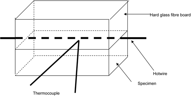
Figure 9 — Transient hot wire set-up
Both the specimen and reference material are pressed by loading to come into close contact with each other.
At the centre of the hot wire, a thermocouple is installed by means of spot welding.
17Care should be taken so that the thermocouple wires have no gap between them because a gap at the junction will lead to the voltage due to the current of the hot wire to be added (or subtracted) to the e.m.f. of the thermocouple.
The thermocouple wires are fitted directly to thermocouple thermometer, which reads in °C. The specimens are placed inside a furnace so that the temperature at which the thermal conductivities are measured may be varied.
| Oven temperature | Thermal conductivity WK-1m-1 | |||||
|---|---|---|---|---|---|---|
| 1 | 2 | 3 | 4 | 5 | Mean value | |
| 200 | ||||||
| 400 | ||||||
| 600 | ||||||
| 800 | ||||||
| 1000 | ||||||
(normative)
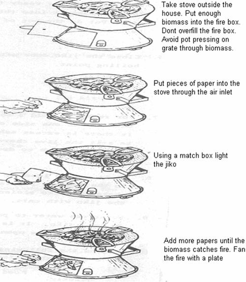
Every biomass stove supplied shall contain operating instructions as illustrated below for its safe and efficient use.

A Comparison of Wood- Burning Cook stoves for Uganda: Testing and Development by Emma George GTZ, 2002
Making and using the Kenya ceramic jiko by ILO/SDSR project with Kenya renewable energy development project, Ministry of Energy
Sazawa charcoal stoves designed for efficient use of charcoal (2003) by C. Pesambili, F. Magessa and N. Mwakabuta Tanzania Traditional Energy Development and Environment Organisation (TATEDO)
Adapted from the revised VITA (1985) International Standards by Patience J. Turyareeba and Muiruri J. Kimani. A manual for Africa, KENGO regional wood energy programme for Africa.
Guidelines for small businesses by Vivienne Abbott, Clare Heyting and Rose Akinyi, Intermediate technology, Kenya 1995
Handbook for the manufacture and use of the paddle mould for the production of ceramic cooking stoves in developing countries, Deutsche Geselischaft fur Tchnische Zusammernabeit (GTZ) GmbH. 423.4 Agricultural farm and household systems
Products that conform to Uganda standards may be marked with Uganda National Bureau of Standards (UNBS) Certification Mark shown in the figure below.
The use of the UNBS Certification Mark is governed by the Standards Act, and the Regulations made thereunder. This mark can be used only by those licensed under the certification mark scheme operated by the Uganda National Bureau of Standards and in conjunction with the relevant Uganda Standard. The presence of this mark on a product or in relation to a product is an assurance that the goods comply with the requirements of that standard under a system of supervision, control and testing in accordance with the certification mark scheme of the Uganda National Bureau of Standards. UNBS marked products are continually checked by UNBS for conformity to that standard.
Further particulars of the terms and conditions of licensing may be obtained from the Director, Uganda National Bureau of Standards.
